Deploying a platform and high availability cluster
The script describes:
- platform installation;
- creating a high availability (HA) cluster with external storage;
- setting up network infrastructure.
To perform the script, you will need:
- valid VMmanager Infrastructure license. The license must include at least 12 CPU cores. Read more in the Licensing article;
- server to install the platform with an Internet connection (P1). Read more in the Server requirements article;
- three servers for Internet-connected cluster nodes (N1, N2, N3). Each server must meet the requirements for cluster nodes and have at least two network interfaces;
- external network storage. Storage can be hardware-based, software-based (e.g., TrueNAS) or Linux-based. It is recommended to use Linux-based storage only for testing the system. The disk space capacity of the storage should be determined taking into account the following needs:
- number of created VMs;
- number of created images and backups of VMs;
- number of operating system templates;
- workstation for remote connection to the servers.
Operation scheme
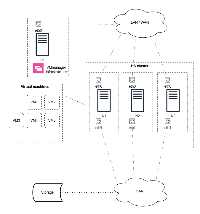
Comments to the scheme:
- P1 — server to install the platform;
- N1, N2, N3 — servers for cluster nodes;
- HA cluster — VMmanager high availability cluster;
- Virtual machines — virtual machines of the cluster;
- Storage — external network storage;
- eth0, eth1 — network interfaces of servers;
- LAN/WAN — networks for interaction between cluster nodes and platform;
- SAN — networks for interaction of cluster nodes with network storage.
Step 1: Preparing the equipment
Workstation
- Make sure that the workstation is connected to the Internet.
- If necessary, install an Internet browser and SSH client.
- Configure the connection to the servers via SSH:
- Open a terminal window or command line.
Create an SSH key:
ssh-keygenCODE- Specify the name and path to the file for SSH keys. By default, on Windows, the SSH key will be stored in C:\Users\<username>\.ssh\, on Unix, in /home/<username>/.ssh/. By default, the private key is saved in id_rsa file, the public key — in id_rsa.pub file.
Add the contents of the public key to the /root/.ssh/authorized_keys file on each server. On Unix systems you can use the command to do this:
ssh-copy-id -i <path_to_key> root@hostBASHComments to the command<path_to_key> — path to the file with the public SSH key
host — IP address or domain name of the remote server
Server for platform installation
- Make sure that you meet all the requirements and recommendations from the Server requirements article.
Synchronize the system time with the NTP server:
ntpdate pool.ntp.orgBASH
External storage
If you are using hardware or software specialized storage, configure it according to the equipment documentation.
If you are using a Linux-based storage system, pre-configure it according to the instructions in the article Pre-configuring SAN.
Servers for cluster nodes
- Make sure that you meet all the requirements and recommendations from the Server requirements for the cluster article.
- Configure the servers to work with the external storage according to the instructions in the article Pre-configuring SAN.
Determine the path to the storage block device via UUID. To do this, run the command:
blkid -o export <device>BASHComments to the command<device> — the path to the block storage device in /dev/disk format. For example, /dev/sdb
Command output example
DEVNAME=/dev/sdb UUID=42d8aa74-143a-454e-b3d2-b719f13b5a22CODEThe path to the device containing the UUID will be /dev/disk/by-uuid/<UUID>. For example, /dev/disk/by-uuid/42d8aa74-143a-454e-b3d2-b719f13b5a22. Save this value. You will need it when you mount the external storage.
Synchronize the system time with the NTP server:
ntpdate pool.ntp.orgBASH
Step 2: Installing the platform
- Save the license activation key (token). If you purchased a license from ISPsystem, go to your personal profile at eu.ispsystem.com → go to Licenses→ open the license information → save the Token value.
Connect to the P1 server via SSH with superuser privileges:
ssh root@hostCODEComments to the commandhost — domain name or server IP address
- Install VMmanager (see the Installation article for detailed instructions):
Download the installer:
curl -O https://download.ispsystem.com/6/installer/vm/vmCODEMake the installer file executable:
chmod +x vmCODERun the installation using the license activation key (token):
./vm installCODEWait for the installation to complete. If the installation is successful, the terminal will display a link to go to VMmanager:
Example of a terminal after successful installation
Link to administrator registration page: https://1.2.3.4/auth/setup?token=C50A0BFA55DEDE3343AABE713022A15FBASH- Open this link in your browser and create the first user:
- Enter the User email.
- Create a Password or click generate to automatically generate a password.
- Click Done.
- Activate the license:
- Click the Setting button in the License not activated window.
- In the License key field enter the value of the Token parameter of your license. You can find it in the Client area eu.ispsystem.com on the license information page.
- Click Activate.
Step 3: Configuring the network
VMmanager contains an address space management module (IPAM). The module manages physical networks, pools and individual IP addresses. When creating a VM, the platform allocates an IP address to it from a specified pool. Therefore, before creating a VM, you must specify the physical network data and configure an IP address pool for the VM.
To configure the network and pool:
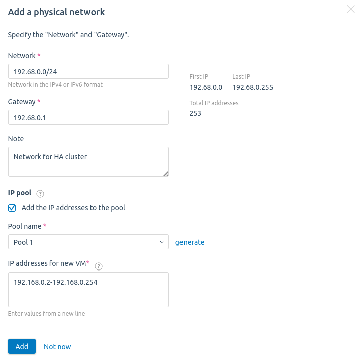
- Go to Networks → Physical networks tab.
- Click the Add a physical network button.
- Specify the Network in the format <network address>/<network mask prefix>. For example, "192.168.0.0/16".
- If necessary, change the IP address of the Gateway.
- Specify an optional Note.
- Enable the Add the IP addresses to the pool option.
- Enter the Pool name — Pool 1.
- Specify the IP addresses for new VM. You can specify:
- individual addresses ("192.168.1.1");
- addresses by mask prefix ("192.168.1.0/24");
- address range ("192.168.1.1-192.168.10.254").
- Click the Add button.
Step 4: Creating a cluster
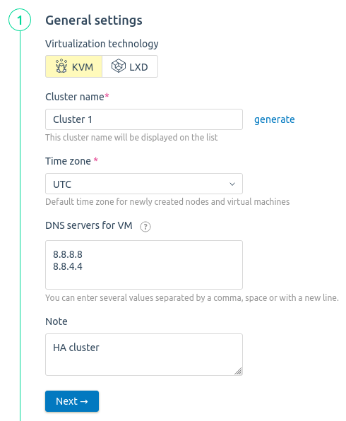
Create a cluster following the instructions in the article Creating a cluster. When creating a cluster:
- Select the Virtualization technology — KVM.
- Specify the Cluster name — Cluster 1.
- Specify the DNS servers for VM. For example, Google Public DNS — 8.8.8.8, 8.8.4.4.
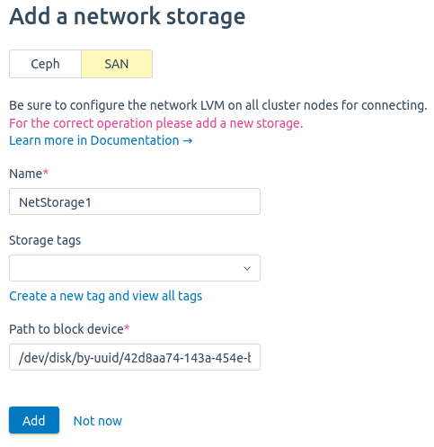
- Add the network storage NetStorage 1 with the SAN type. Specify the Path to block device received when preparing the nodes in Step 1.
- No local storage should be connected to the HA cluster. To remove the default local file storage, in the Storage1 widget, click the
 icon.
icon.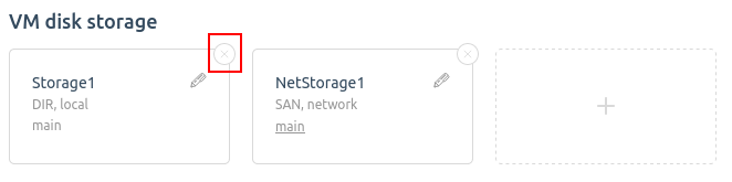
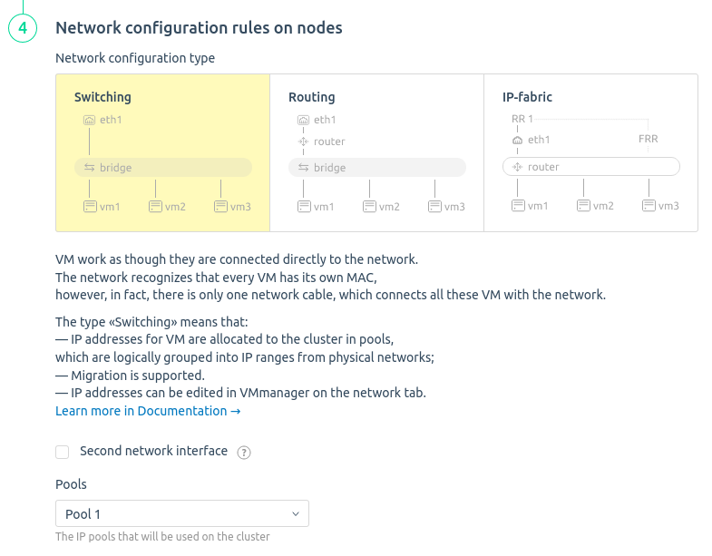
- Select the Network configuration type — Switching.
- In the Pools field, select the pool created in Step 3 — Pool 1.
Step 5: Adding nodes to the cluster
- In the platform interface, go to the Nodes section.
- Click the Connect a node button.
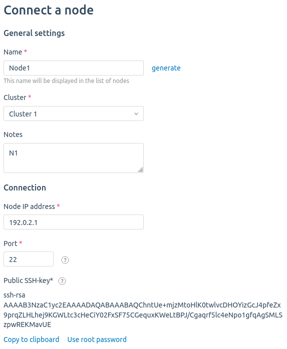
- Specify the node settings:
- Enter the cluster node Name — Node 1.
- Select the Cluster to which the node will be connected — Cluster 1.
- Specify the IP address of the N1 server and the Port for SSH connection. If you have not changed the SSH settings on the host, leave the default value.
- Click the I want to use public SSH-key button and save the contents of the key.
- Connect to the N1 server via SSH and add the contents of the public key to the /root/.ssh/authorized_keys file.
- Leave the other settings at their default values.
- Click the Connect the node button.
- Perform steps 2-4 for N2 and N3 servers. Specify Node 2 and Node 3 as the node name.
Step 6: Configuring the network infrastructure
- Configure VLANs to separate management traffic, VMs traffic and storage connectivity. To separate traffic within the same physical interface, create the necessary bridges on the cluster nodes. Read more in Network setting on the cluster node article.
- Allow traffic to transfer between the created VLANs on the switch ports to which the equipment is connected.
Configure mapping between the network interfaces connected to the SAN and the network storage.
Configure the network storage connection using multipath technology.
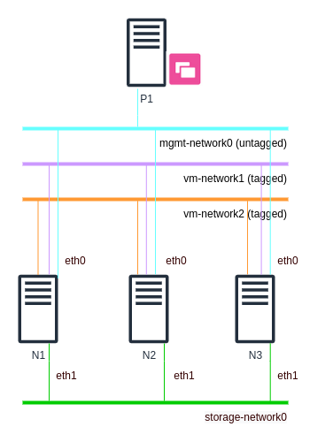
Example of a network scheme
Comments to the scheme:
- P1 — server with the platform;
- N1, N2, N3 — cluster nodes;
- mgmt-network0 (untagged) — network for management traffic of cluster nodes (untagged traffic);
- vm-network1, vm-network2 — networks for VMs traffic (tagged traffic);
- storage-network0 — network for external storage connection traffic;
- eth0, eth1 — network interfaces on cluster nodes.
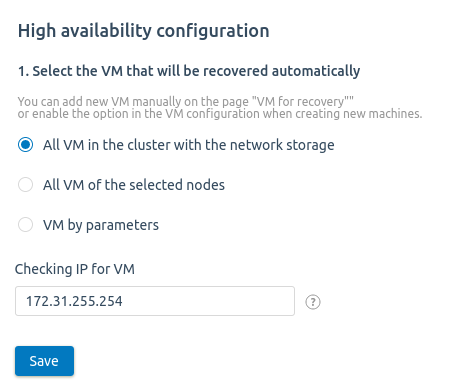
Step 7: Configuring high availability
- Go to Clusters → select the cluster → High availability.
- Click the Enable high availability button.
- Specify settings:
- Enable the option All VMs in the cluster with the network storage.
In the Checking IP for VM field enter the IP address, which will be used to check connectivity.

If all nodes have the same gateway, specify the gateway IP address. If not, the external IP address. For example, 8.8.8.8.
- Click the Save button.
Step 8: High availability check
- Create 5 VMs according to the instructions in the Creating a virtual machine article. Select Node 1 as the cluster node.
- Shut down the N1 server. If high availability is configured successfully, the platform will restore the VMs on Node 2 and Node 3.